
To avoid unexpected breakdowns, costly repairs and subsequent losses due to motor downtime, it is important that the electric motor is fitted with some sort of protective device. Motor protection can be divided into the following 3 levels: (a) External protection against short circuit (b) External protection against overload (c) Built-in motor protection.
The basic electric motor protection scheme is shown below:

External protection against short circuit in the whole installation - External protection device is normally done using different types of fuses or short circuit relays. This kind of protection device is compulsory and legal and placed under safety regulations.
External protection against overload of specific equipment - This type of protection is given to the electric motor to avoid overload and thereby prevent damage and breakdown of the motor. This type of protection reacts on current. Note that overload of electric motors are a common cause of failure of motors.
Built-in motor protection - This is usually done with thermal overload protection to avoid damage and breakdown of motor. The built-in protector always requires an external circuit breaker while some built-in motor protection types even require an overload relay. There are two types commonly used namely: (i) Thermostats (ii) Thermistors or Positive Temperature Coefficient Sensors (PTC).
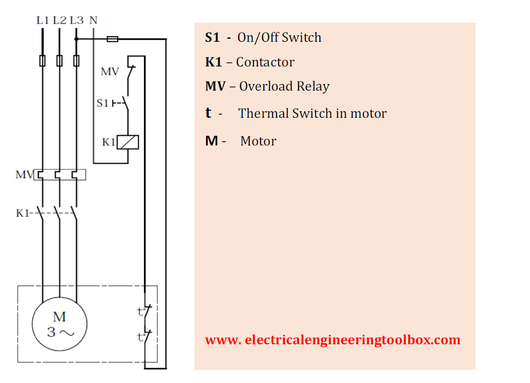
Thermostats - Thermostats are in-built protection devices that are used in protecting an electric motor. With three-phase motors, thermostats are considered unstable protection against stall or other rapidly changing temperature conditions. In single phase motors thermostats do protect against locked-rotor conditions. Please note, Thermal switches cannot protect against locked- rotor conditions. The electric motor wiring diagram below illustrates internal motor protection by a thermal switch like the thermostat:
Thermistors Or Positive Temperature Coefficient Sensors (PTC)

Thermal protection is then achieved by monitoring the temperature of the motor windings with PTC sensors. If the windings exceed the rated trip temperature, the sensor undergoes a rapid change in resistance relative to the change in temperature.
As a result of this change, the internal relays de-energize the control coil of the external line break contactor. As the motor cools and an acceptable motor winding temperature has been restored, the sensor resistance decreases to the reset level. At this point, the module resets itself automatically, unless it was set up for manual reset.
Note that the thermistor has to be connected to a control circuit, which can convert the resistance signal, which again has to disconnect the motor. They are commonly used in the internal windings of three-phase motors for thermal protection. The wiring diagram below illustrates the implementation of thermistor motor thermal protection in a three-phase motor:

PTC Sensors Lead identification
|
Nominal Response
temperature (degree C) |
145 |
150 |
155 |
160 |
165 |
170 |
|
Coloured
Leads |
White |
Black |
Blue |
Blue |
Blue |
White |
|
Black |
Black |
Black |
Red |
|
Green |
|
Symbol |
Technical Overload (1 digit) |
Number of levels and function area (2 digits) |
Category (3 digits) |
|
TP 111 |
Only slow, constant overload |
1 Level at cut off |
1 |
|
TP 112 |
2 |
||
|
TP 121 |
2 Levels at emergency signal and cut
off |
1 |
|
|
TP 122 |
2 |
||
|
TP 211 |
Slow and fast, applies to constant
overload and blocked condition |
1 Level at cut off |
1 |
|
TP 212 |
2 |
||
|
TP 221 |
2 Levels at emergency signal and cut
off |
1 |
|
|
TP 222 |
2 |
||
|
TP 311 |
Only fast, applies to blocked
condition |
1 Level at cut off |
1 |
|
TP 312 |
2 |
|
|
Common Fault Conditions For Electric Motor Protection |
|
1 |
Problems with the power supply quality: –
Overvoltage – Undervoltage – Imbalanced voltages/currents – Frequency variation |
|
2 |
Installation, Supply and Motor Failures |
|
3 |
Slowly developing temperature rise: – Insufficient cooling – High ambient temperature – High altitude operation – High liquid temperature – Too high viscosity of the pumping liquid – Frequent starts – Too big load inertia (not common for pumps) |
|
4 |
Quickly developing temperature rises: – Locked rotor – Phase breakage
|