
What is a Contactor?
A contactor is an electrical device used for switching an electrical circuit on or off. It is similar to a relay, but the main difference is that the contactor is applied in high current carrying capacity applications and the relay used for low current applications.
Generally, these electrical devices feature multiple contacts. These contacts are in most cases normally open and provide operating power to the load when the contactor coil is energized. Contactors are mostly used for controlling electric motors.
There are various types of contactors, and each type has its own set of features, capabilities, and applications. Contactors can break current over a wide range of currents, ranging from a few amperes to thousands of amperes, and voltages from 24 VDC to thousands of volts. In addition, these electrical devices come in various sizes, from palm dimensions to sizes measuring a meter or yard on one side (approximately).
The most common application area of the contactor is high-current load. Contactors are known for their capability to handle currents of over 5,000 amperes and high power over 134Hp
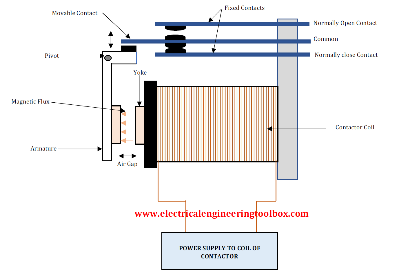
Main Components of the ContactorThe electrical contactor has three (3) main components namely the (i) Coil (Electromagnet) (ii) Enclosure (iii) Contacts.
The Coil or Electromagnet provides the driving force that is required to close the contacts of the contactor. The coil and contacts are protected by an enclosure.
The enclosure provides insulation and protection from personnel touching the contacts. The protective enclosure is made from different materials, such as polycarbonate, polyester, Nylon 6, Bakelite, thermosetting plastics, and others.
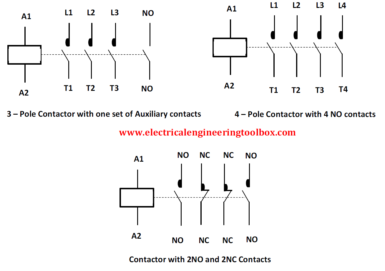
The contacts of the contactor are responsible for carrying rated current to the load the contactor powers. There are different types of contacts in a contactor namely, contact springs, auxiliary contacts, and power contacts. Each type of contact has an individual role to play.
|
NEMA CONTACTOR
AND MOTOR STARTER SIZES |
||||
|
NEMA Size |
Max. Continuous Current (A) |
Max. HP at 200V AC |
Max.
HP at 230V AC |
Max. HP at 480/575V AC |
|
00 |
9 |
1.5 |
1.5 |
2 |
|
0 |
18 |
3 |
3 |
5 |
|
1 |
27 |
7.5 |
7.5 |
10 |
|
2 |
45 |
10 |
15 |
25 |
|
3 |
90 |
25 |
35 |
50 |
|
4 |
135 |
40 |
50 |
100 |
|
5 |
270 |
75 |
100 |
200 |
|
6 |
540 |
150 |
200 |
400 |
|
7 |
810 |
- |
300 |
600 |
|
8 |
1215 |
- |
450 |
900 |
|
9 |
2250 |
- |
800 |
1600 |
|
IEC UTILIZATION
CATEGORIES |
|||
|
LOW VOLTAGE
UTILIZATION CATEGORIES |
|||
|
Nature of Current |
Category |
Typical Applications |
Relevant IEC product category |
|
A.C |
AC-1 |
Non-inductive or slightly inductive loads, resistance furnaces. |
60947-4 |
|
AC-2 |
Slip-ring motors: starting, switching off. |
||
|
AC-3 |
Squirrel-cage motors: starting, switching off motors during running. |
||
|
AC-4 |
Squirrel-cage motors: starting, plugging1, inching2 |
||
|
AC-5a |
Switching of electric discharge lamp control. |
||
|
AC-5b |
Switching of incandescent lamps. |
||
|
AC-6a |
Switching of transformers. |
||
|
AC-6b |
Switching of capacitor banks. |
||
|
AC-7a |
Slightly inductive loads in household appliances and similar
applications. |
||
|
AC-7b |
Motor-loads for household applications. |
||
|
AC-8a |
Hermetic refrigerant compressor motor control with manual resetting of
overload releases. |
||
|
AC-8b |
Hermetic refrigerant compressor motor control with automatic resetting
of overload releases. |
||
|
AC-12 |
Control of resistive loads and solid-state loads with isolation by
optocoupler. |
60947-5 |
|
|
AC-13 |
Control of solid-state loads with transformer isolation. |
||
|
AC-14 |
Control of small electromagnetic loads. |
||
|
AC-15 |
Control of A.C electromagnetic loads. |
||
|
AC-20 |
Connecting and disconnecting under no-load conditions. |
60947-3 |
|
|
AC-21 |
Switching of resistive loads, including moderate overloads. |
||
|
AC-22 |
Switching of mixed resistive and inductive loads, including moderate
overloads. |
||
|
AC-23 |
Switching of motor loads or other highly inductive loads. |
||
|
A.C and D.C |
A |
Protection of circuits, with no rated short-time withstand current. |
60947-2 |
|
B |
Protection of circuits, with a rated short-time withstand current. |
||
|
D.C |
DC-1 |
Non-inductive or slightly inductive loads,
resistance furnaces. |
60947-4 |
|
DC-3 |
Shunt-motors, starting, plugging1, inching2,
dynamic breaking of motors. |
||
|
DC-5 |
Series-motors, starting, plugging1, inching2,
dynamic breaking of motors. |
||
|
DC-6 |
Switching of incandescent lamps. |
||
|
DC-12 |
Control of resistive loads and solid-state loads
with isolation by optocouplers. |
60947-5 |
|
|
DC-13 |
Control of D.C electromagnets. |
||
|
DC-14 |
Control of D.C electromagnetic loads having economy
resistors in circuit. |
||
|
DC-20 |
Connecting and disconnecting under no-load
conditions. |
60947-3 |
|
|
DC-21 |
Switching of resistive loads, including moderate
overloads. |
||
|
DC-22 |
Switching of mixed resistive and inductive loads,
including moderate overloads, (e.g. shunt motors). |
||
|
DC-23 |
Switching of highly inductive loads, (e.g. series
motors). |
||
|
1By plugging is understood stopping or reversing the motor
rapidly by reversing motor primary connections while the motor is running.
2By inching (jogging) is understood energizing a motor once or
repeatedly for short periods to obtain small movements of the driven
mechanism.
|
|||
|
Source: ©International
Electrotechnical Commission |
|||
Difference between NEMA and IEC Contactors
Below is a comparison between NEMA and IEC contactors already discussed:
|
IEC |
NEMA |
|
Less Expensive |
More Expensive |
|
More Compact |
Larger design |
|
Global Market |
North American Market |
|
Less versatile: IEC contactors are specific
application requirements |
More versatile: A NEMA contactor can cover a broader
range of applications |
|
Finger Safe |
Safety covers required |
|
Faster reaction to overloads |
Can handle short circuits better |
Contactor Terms and Ratings
The table gives explanation of the common terms and ratings used with contactors designed based on the IEC global standard:
| Circuits | Auxiliary circuit All the conductive parts of a contactor designed to be inserted in a different circuit from the main circuit and the contactor control circuits. Control circuit All the conductive parts of a contactor (other than the main circuit and the auxiliary circuit) used to control the contactor's closing operation or opening operation or both. Main circuit All the conductive parts of a contactor designed to be inserted in the circuit that it controls. |
| Coil operating range | Expressed as a multiple of the rated control circuit voltage Uc for the lower and upper limits |
| Cycle time | This is the sum of the current flow time and the no-current time for the given cycle. Electrical durability Number of on-load operating cycles that the contactor is able to carry out. It depends on the operational current, the operational voltage, and the utilization category. Mechanical durability Number of no-current operating cycles that a contactor can carry out. |
| Endurance/durability | Electrical endurance The number of on-load operating cycles (i.e., with the current on the main contacts) a contactor can achieve, varies depending on the utilization category. Mechanical endurance The number of off-loading operating cycles (i.e., without current on the main contacts) a contactor can achieve. |
| Inching | Energizing a motor once or repeatedly for short periods to obtain small movements of the driven mechanism. |
| Intermittent Duty | Duty in which the main contacts of a contactor remain closed for periods of time insufficient to allow the contactor to reach thermal equilibrium, the current-carrying periods being separated by off-load periods of sufficient duration to restore equality of temperature with the cooling medium. |
| Rated breaking capacity. Rated making capacity |
Value of RMS current a contactor can break or make at a fixed voltage value, within the conditions specified by the standards, depending on the utilization category. |
| Rated control circuit voltage Uc |
Control voltage value for which the control circuit of the unit is sized. |
| Rated insulation voltage Ui | Voltage value which designates the unit and to which dielectric tests, clearance, and creepage distances are referred. |
| Rated impulse withstand voltage, Uimp | The highest peak value of an impulse voltage of prescribed form 1.2/50, which does not cause breakdown under specified test conditions. |
| Rated operating current Ie | Current value stated by the manufacturer and considering the rated operating voltage Ue, the rated frequency, the rated duty, the utilization category, the electrical contact life and the type of protective enclosure. |
| Rated operating voltage Ue | Voltage value to which utilization characteristics of the contactor are referred, i.e., phase to phase voltage in 3 phase circuits. |
| Conventional thermal current Ith |
Value of current the contactor can withstand with poles in closed position, in free air for an eight-hour duty, without the temperature rise of its various parts exceeding the limits specified by the standards. |
| Making and breaking current |
Current at contactor closing or at contactor opening. |
| Resistance to shocks | Requirements applicable for instance to vehicles, crane operation or switchgear slide-in module systems. At the quoted permissible «g» values, contactors must not undergo a change in switching state and overload relays must not trip. |
| Resistance to vibration | Requirements applicable to all the vehicles, vessels and other similar transport systems. At the quoted amplitude and vibration frequency values, the unit must be capable to achieve the required duty. |
| Times | Closing time Time between energization of the coil until the moment the contacts of the first current path to be closed, actually close. Opening time Time between de-energization of the coil until the moment when the contacts of the last current path to be opened are open. Minimal operation time Shortest control duration to ensure complete closing or opening of a contactor. Short time current permissible Value of current which the contactor can withstand in closed position for a short time period and within specified conditions. Time constant Ratio of inductance to the resistance: L/R = mH/Ohm = ms. Cycle duration Total time of the on-load + off-load period. |